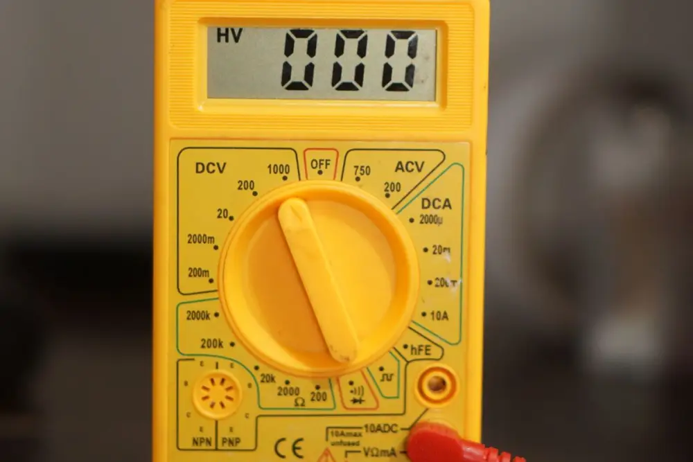
A basic digital multimeter costs little and finds most faults. You can check a wire, a fuse, a diode, a transistor or a capacitor in under a minute. This guide covers the tests you will use every week and the mistakes to avoid.
Know your meter
| Dial marking | Meaning |
|---|---|
| DCV or V with a straight line | DC voltage: batteries, adaptors, circuit rails |
| ACV or V with a wavy line | AC voltage: mains and transformer output |
| Ω | Resistance |
| Diode symbol and sound wave | Diode test and continuity beep |
| hFE | Transistor gain socket on some meters |
| A or mA | Current. The meter must be in series with the circuit. |
1. Continuity test
Use this to check wires, fuses, switches, PCB tracks and solder joints.
- Switch the circuit off and remove power.
- Turn the dial to the continuity or diode position (the one with the sound symbol).
- Touch the probes together. The meter should beep. This proves the meter and leads work.
- Touch the probes to each end of the wire or track.
- A beep (and a low reading) means the path is connected. No beep and OL means it is broken.
2. Diode test
The same dial position shows the forward voltage drop of a diode.
| Connection | Silicon diode | LED |
|---|---|---|
| Red on anode, black on cathode | About 0.5 to 0.7 V | Roughly 1.6 to 3 V, may glow dimly |
| Reversed | OL | OL |
Reading in both directions means the diode is shorted. OL in both directions means it is open. Both mean replace it.
3. Checking capacitors
Always switch off and discharge the capacitor first, especially large ones from a power supply or fan.
If your meter has a capacitance (Cx) range
- Remove the capacitor from the circuit or lift one leg.
- Select the capacitance range and connect the leads. For polarised electrolytics, red goes to the positive leg.
- Compare the reading with the value printed on the body. Electrolytics often read a little different from the label, but one far below or reading zero is faulty.
If your meter only has a resistance range
- Set the dial to a high resistance range such as 20 k or 200 k.
- Connect the leads to a discharged electrolytic. The reading should start low and climb towards OL as the capacitor charges.
- A reading that stays near zero means shorted. A reading that stays at OL from the start suggests open, or a very small capacitor.
For a ceiling fan capacitor, see our fan capacitor guide.
4. Testing a transistor
Use the diode test. Think of a transistor as two diodes sharing the base.
| Test | Good NPN | Good PNP |
|---|---|---|
| Base to emitter, forward | Red on base, black on emitter: about 0.5 to 0.8 V | Black on base, red on emitter: about 0.5 to 0.8 V |
| Base to collector, forward | Red on base, black on collector: similar drop | Black on base, red on collector: similar drop |
| Reverse of both | OL | OL |
| Collector to emitter, both ways | OL | OL |
If you do not know the pinout, look up the datasheet, since pin order differs between types. If your meter has an hFE socket, you can plug the transistor in and compare gain with a known good part of the same type.
5. Resistance
Turn the dial to the ohms range above the expected value, then touch the probes to both legs. Lift one leg out of the board first or other parts will change the reading. The colour code gives the expected value, see the resistor colour code guide.
Common mistakes
- Measuring current with the leads left in the 10 A socket and then measuring voltage with them there.
- Testing a part on a powered board.
- Holding both metal tips with your fingers while measuring resistance, which adds your body resistance.
- Forgetting to discharge a capacitor before testing.
- Leaving the meter on a current range and then probing a power rail.
Get a meter and parts
Konark Radio Centre in Ashok Nagar, Bhubaneswar, supplies electronic components and tools for students and technicians. Ask on WhatsApp or visit the shop. For first builds, see our project kits.
Frequently asked questions
Why does my meter show OL or 1 on the left?
It means over limit, an open circuit or a value too large for the selected range. In continuity and diode tests, OL is what you expect when nothing is conducting.
Can I measure resistance in a live circuit?
No. Switch the circuit off and, for a resistor, lift one leg. A powered circuit gives wrong readings and can damage the meter.
My meter has no capacitance range. Can I still test a capacitor?
Partly. For a large electrolytic, use the resistance range and watch the reading climb as it charges, then reverse the leads. It shows if the capacitor is shorted or open, but not its exact value.
Which lead goes where?
The black lead goes in the COM socket. The red lead goes in the socket marked for volts, ohms and milliamps for most tests. Use the separate 10 A socket only for measuring large currents, and move the lead back afterward.
Need the parts?
Send the parts list on WhatsApp or walk in. Plot No. 39/F, Ashok Nagar, near Sreeleathers, open 10 AM to 9 PM, all 7 days.